Event-driven process chain: EPK definition, rules and examples
The event-driven process chain (EPC): definition, relevant symbols & objects, application rules, an EPC example incl. guide and more ✅.
The "technical drawing" (also production drawing, construction drawing) is colloquially referred to as the "language" of engineers. It is a graphic document that is primarily used in mechanical and plant engineering. It contains all the information required for the manufacture of individual parts or the assembly of subassemblies or a complete machine in written form.
1. Technical drawing definition
2. History and field of application
3. Basics of technical drawing
4. Rules and standards in drawing
5. The representation of the technical drawing (views)
6. Free programs for technical drawing
7. Frequently asked questions (FAQ) about technical drawings
The technical drawing is part of the technical product documentation. It is mainly used in mechanical and plant engineering. In addition, a type of technical drawing is used in the construction industry. Here one speaks however then of a construction drawing.
In DIN 199 of the German Institute for Standardization, the technical drawing is defined as follows:
"A technical drawing is a drawing of the type and completeness required for technical purposes, e.g., by adherence to rules of representation and dimensional entries."
This quotation underscores the complexity of the process demanded of the clean execution of such a technical drawing.
The foundations of geometry can be traced back to ancient Greece to various mathematicians. The beginning of technical drawing, on the other hand, dates back to the 15th century. The pioneer of technical drawing is none other than Leonardo da Vinci, who wrote down his inventions and ideas.
In more recent history, more frequent records related to technical drawing can be found. For one, records of a French pioneer of flight were found in the early 17th century. Secondly, in the 19th century, references can be found in various written down patents.
Nowadays, there are countless rules, standards, forms of representation, recommendations for dimensions, typeface or line style. Parallel to this, the type and variety of tools for making a technical drawing also changed. Instead of drawing boards, curve rulers and stencils, computer-aided design (CAD) programs are used.

The progress in today's technology thus offers enormous advantages for technical drawing. With the help of 3D CAD systems, three-dimensional bodies can also be created and final drawings derived.
A technical drawing is the graphic representation of all the information it takes to produce a component or assembly. The difficulty of an engineering drawing is to generate all the information without possible misunderstandings. Precision and unambiguity in the information are mandatory so that the reader can understand the engineering drawing without difficulty.
Such a technical drawing is usually made from different views and angles so that all relevant information can be accommodated. Nevertheless, it happens that additional sectional views are necessary in order to make possibly hidden geometries of components or assemblies visible. The technical drawing is generally divided into the drawing margin, the drawing area and a title block. Assemblies require a parts list, which is ideally located above the title block.
Usually, the paper size for technical drawings varies between A4 and A0. Furthermore, there are various scales to realize a technical drawing. With a scale of 2:1 ("two to one"), an assembly or component is enlarged. If, on the other hand, you draw on a scale of 1:2, the object to be drawn is reduced in size. The object drawn at a scale of 1:2 is therefore only half as large as it is in reality.
Es gibt viele unterschiedliche Arten und Herangehensweisen, eine technische Zeichnung anzufertigen. Diesbezüglich wird besonders im Hinblick auf die Vollständigkeit einer solchen Darstellung unterschieden. Man unterscheidet zwischen Teilzeichnungen und Zusammenbauzeichnungen. Daraus ergeben sich folgende Varianten einer technischen Zeichnung:
There are many different ways and approaches to make a technical drawing. In this regard, a distinction is made especially with regard to the completeness of such a representation. A distinction is made between partial drawings and assembly drawings. This results in the following variants of a technical drawing:
A general drawing is the complete representation of a machine, an apparatus or a device. A group drawing represents the representation of a group of components. In contrast, the individual part drawing represents a single component or individual part. The single part drawing can be further subdivided into different types of drawings (blank drawing, arrangement drawings and model drawings). A schematic drawing is a two-dimensional drawing that is not to scale. It is used to represent the logical structure of a building system.
The drawing sheet is divided into different shapes according to DIN 476. The distance from the edge of the drawing sheet to the drawing is 5 mm. The dimensions of DIN-A are as follows:
The pages of the drawing sheet relate width to length as 1 to root 2.
Dimensioning is one of the most important components of technical drawing. Without correct and proper dimensioning, technical drawings cannot be reproduced. DIN 406-10 and DIN 406-11 describe the rules for inserting dimensions properly in technical drawings.
Dimensioning is used to describe the length, height, width and diameter of an object. The correct insertion of dimension lines, the dimension number, the dimension auxiliary line and the dimension arrows ensures technically correct dimensioning.
Furthermore, dimensioning distinguishes between different areas of application. Functional planning uses the functional dimensions. Production, on the other hand, requires manufacturing dimensions and workpiece inspection is carried out according to the inspection dimensions. A distinction is also made between position dimensions, form dimensions and basic dimensions.
The position dimensions indicate the exact position of the change. The form dimensions are responsible for the size of the recess. The basic dimensions are used to specify the height, width and depth of a workpiece.
According to the rules of dimensioning, the same must be done outside the workpiece.
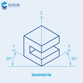
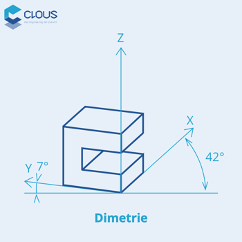
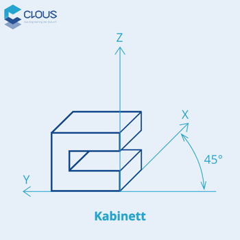
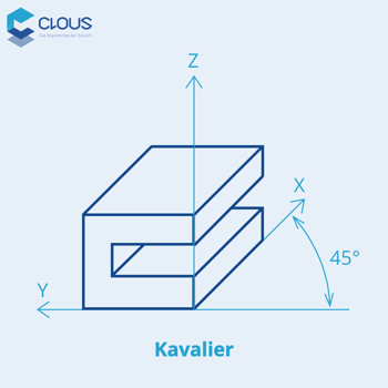
The design of spatial images in technical drawing is done by different projections. Isometric projection and Dimetric projection, as well as Cavalier and Cabinet projection are the most commonly used. The projections differ in their different angles of the axes.
Isometric projection
|
 |
Dimetric projection
|
 |
Cabinet projection
|
 |
Cavalier projection
|
 |
Technical drawings make use of different types of lines, each of which is responsible for different tasks.
The subject of the representation of a technical drawing also includes the different sections that are required. There are three different types of sections: full section, half section and partial section. With a full section, the front half of the workpiece is cut out. With a half cut, on the other hand, the lower quarter is cut out. In case only certain parts are needed, a partial cut is used.
Before the computer as a digital tool, technical drawings were made by hand on paper. The illustration was reproduced with the aid of tracings. Therefore, the originals always had to be carefully stored.
Nowadays, this process is done with the support of CAD programs. This means that the technical drawings are now available digitally and can also be printed out. Theoretically, therefore, paper can be dispensed with completely. Production machines are controlled directly by CAD and CAM software. In addition, different views of a drawing can be created directly in the program, viewed and then printed if desired.
File formats such as DXF, IFC or DWG are used for archiving drawings. Microfilms are used for long-term archiving. Over several centuries, this cannot be guaranteed with digital options.
SketchUp Free is a browser-based online program that is free under restrictions. Both 2D and 3D models can be created and saved.
To use the software, they need to create an account. There are three different options for this: the Free, Shop and Pro versions, all of which offer different functions. The operation of the program is very user-friendly, all important functions can be found quickly.
All in all, the program is easy to use and is excellent for simple designs. Unfortunately, the creation of a real technical drawing is only possible in the paid version.
Click here for the free technical drawing program.
FreeCAD CAD program is a parametric 3D design program. It was developed for use in architecture, plant engineering, mechanical engineering, production design. 2D designs can also be created.
Functions such as dimensions, fits, tolerances and surface finishes are available. With the help of the program, technical drawings can be created quickly and easily. The program is a free open source project and is available for Windows, Mac and also Linux.
All in all, FreeCAD is a user-friendly program that can be extended with add-ons. Formats such as STEP, IGES, STL, SVG, DXF, OBJ, IFC and DAE can be edited.
Click here to get the free program for making technical drawings.
NanoCAD 5 is a free 2D drawing program for technical drawing. The user interface and operation is based on the point+click method common for 2D drawing programs. The program is suitable for simple drawings. For professional projects, however, you should buy the paid variant nanoCAD Pro.
Click here for the free technical drawing program.
TurboCAD 2D is a popular program for designs and drawings. It is suitable not only for mechanical engineers, but also for architects and other professionals.
With the help of TurboCAD 2D it is possible to create assembly drawings, single part drawings, manufacturing drawings, assembly drawings, etc. The program is available through free registration. Since it is a pure 2D drawing program, you have to draw the lines and geometric shapes yourself.
TurboCAD 2D is an excellent program for 2D drawings. To get more features, you can purchase the paid version. A small disadvantage of the free version is the in-house formats in which you save and import your projects. Nevertheless, it is possible to print the drawings as PDF.
Click here to get the free technical drawing program.
QCAD is an open source drawing and sketching program. To create decent technical drawings, the unfamiliar operation requires some practice.
QCAD is a free program. You can create designs on different layers, so you can better structure the design. Unfortunately, it is not possible to create parametric 3D constructions and you are forced to create isometric views yourself.
With QCAD it is possible to create created projects in different formats. These formats include DXF R15, SVG (import), PDF (export), BMP, JPEG, TIFF, ICO, PPM, XPM, and XBM.
For 2D drawings, QCAD is excellent.
Click here for the free technical drawing program.
A technical drawing is a graphical representation that is preferably found in mechanical and plant engineering. Colloquially, it is referred to as the "language of engineers". Technical drawings contain all the information needed to create or assemble a machine.
A technical drawing can be made manually (analog) or digitally on a computer using a CAD program. This allows the drawings to be created directly in 2D and 3D formats. In addition, a transformation from 3D to 2D is possible. In addition to many paid tools, there are also some good, free programs for making a technical drawing.
Technical drawings are mainly used in mechanical and plant engineering. In addition, there is also a form of technical drawing (construction drawing) in the building industry. Various professions such as architects, draftsmen, engineers, designers and technical draftsmen use technical drawings for their work.
There are several free programs for technical drawings on the market. For example, SketchUp Free, FreeCAD - 2D/3D design software, nanoCAD5, TurboCAD 2D - 2D CAD drawing program or QCAD - 2D drawing program.
The event-driven process chain (EPC): definition, relevant symbols & objects, application rules, an EPC example incl. guide and more ✅.
Information about DXF file | Structure, development and shortcomings of the Drawing Interchange File Format. What is a DXF file & how do I open it?
Simultaneous engineering is a method to shorten the time from the idea of the product to the market launch.